

The short answer: Static timing analysis (STA) checks that every timing path in a synchronous design meets its timing requirements, without simulation vectors. It breaks the design into paths that start at an input port or a register clock pin and end at an output port or a register data pin, adds up cell and wire delays along each path, and compares the arrival time with the time the data is required. Because it checks every path at the worst and best delays, it’s exhaustive, fast, and the standard way to sign off timing.
Simulation tells you whether a design does the right thing; STA tells you whether it does it fast enough, and safely enough, at every corner. This is the first post in my STA series. I’ll start with what STA is and how it sees a design: as a set of timing paths.
- Why static, and not simulation?
- Timing paths
- How STA computes timing
- What STA checks
- Tools
- This series in order
Table of Contents
Part 1: Why static, and not simulation?
| Timing simulation | Static timing analysis | |
|---|---|---|
| Needs test vectors | Yes | No |
| Coverage | Only paths the vectors exercise | Every path |
| Speed on large designs | Very slow | Fast |
| Checks functionality | Yes | No: assumes the logic is correct |
| Depends on | Testbench quality | Correct constraints (SDC) |
The catch is in the last row: STA is only as good as its constraints. A missing clock or a wrong exception can hide a real failure.
Part 2: Timing paths
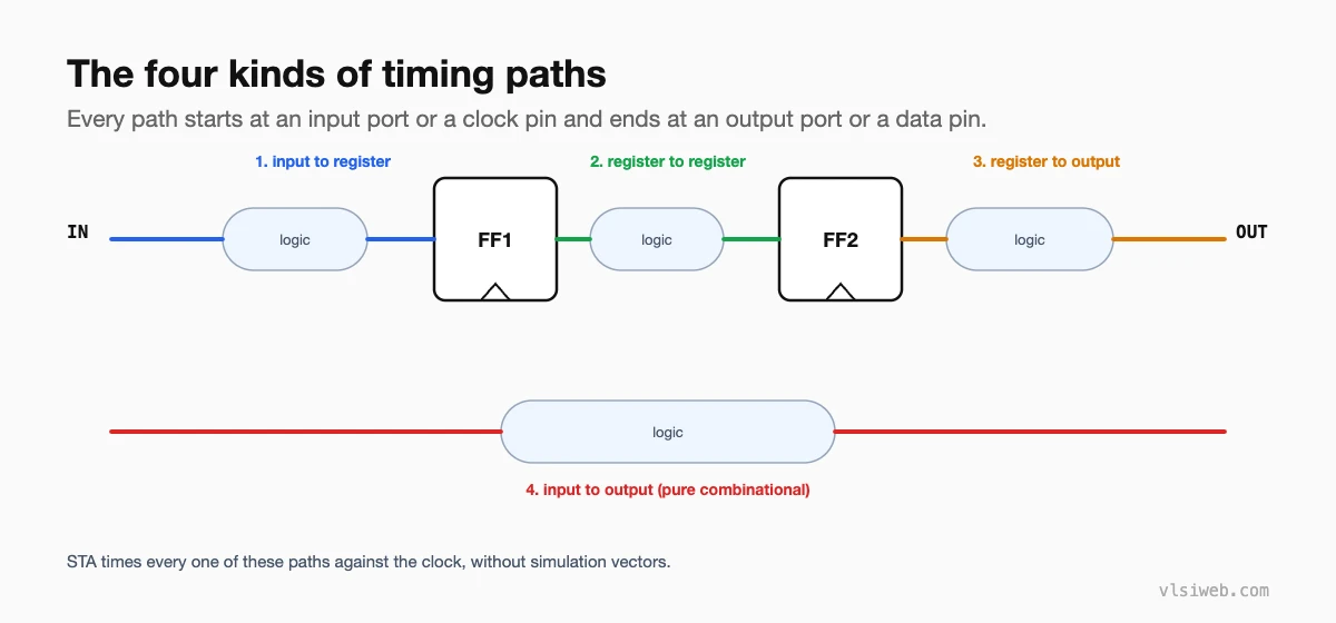
- Startpoints: input ports and clock pins of sequential cells.
- Endpoints: output ports and data pins of sequential cells (plus a few special checks such as clock gating and recovery/removal).
- Register-to-register paths are fully inside the block; paths to and from ports depend on input and output delay constraints that describe the outside world.
- Clock paths are analysed separately from data paths; their delays (latency, skew) enter the setup and hold calculations.
Part 3: How STA computes timing
- Each cell’s delay comes from its library (Liberty) tables, looked up by input slew and output load.
- Each wire’s delay comes from extracted or estimated parasitics.
- Delays add up from startpoint to endpoint to give the arrival time; the clock and the check (setup or hold) give the required time.
- Slack = required − arrival for setup (the other way round for hold). Negative slack is a violation.
The next posts go through each of these in detail.
Part 4: What STA checks
| Check | Purpose |
|---|---|
| Setup | Data arrives early enough for the next clock edge |
| Hold | Data doesn’t change too soon after the current edge |
| Recovery / removal | Asynchronous reset release is timed correctly |
| Clock gating | Enables are stable around clock gating cells |
| Max transition, capacitance, fan-out | Cells operate inside their characterised range |
| Min pulse width, min period | Clocks are clean enough for the flops |
Part 5: Tools
Synopsys PrimeTime and Cadence Tempus are the standard sign-off tools; P&R and synthesis tools include their own timers. OpenSTA is a capable open-source engine used in OpenROAD. For interview-style practice, see my STA interview questions.
Part 6: This series in order
- What is STA? Timing paths
- Setup and hold checks
- Arrival time, required time and slack
- Cell and wire delay calculation
- Clocks in STA: latency, skew, jitter
- SDC timing constraints
- False paths and multicycle paths
- Corners, OCV and variation
- Reading timing reports and debugging violations
- Clock gating checks
- Latch timing and time borrowing
Practise this on VLSI Forge
I built VLSI Forge so you can write RTL in your browser, run it on a real simulator and check every signal in the waveform. Free, nothing to install.
Static Timing Analysis problems · Daily challenge
Next: Setup and hold checks.
FAQ
What is static timing analysis?
A method of checking that every timing path meets setup, hold and other timing requirements, by adding up delays instead of simulating vectors.
What are the four types of timing paths?
Input to register, register to register, register to output, and input to output.
What are startpoints and endpoints?
Startpoints are input ports and clock pins of sequential cells; endpoints are output ports and data pins of sequential cells.
Does STA check functionality?
No. It assumes the logic is correct and only checks timing. Functional correctness comes from simulation and formal verification.
