

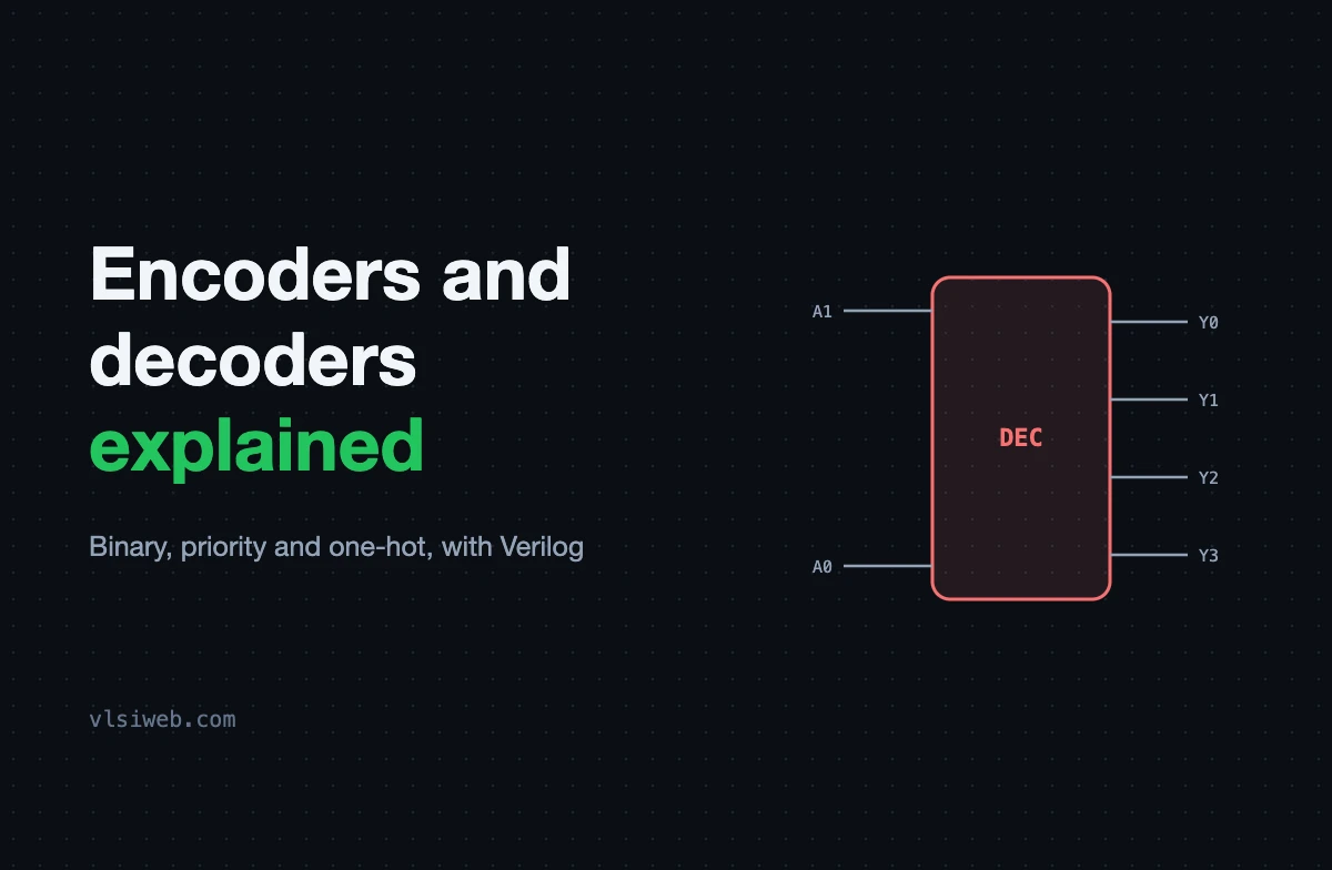
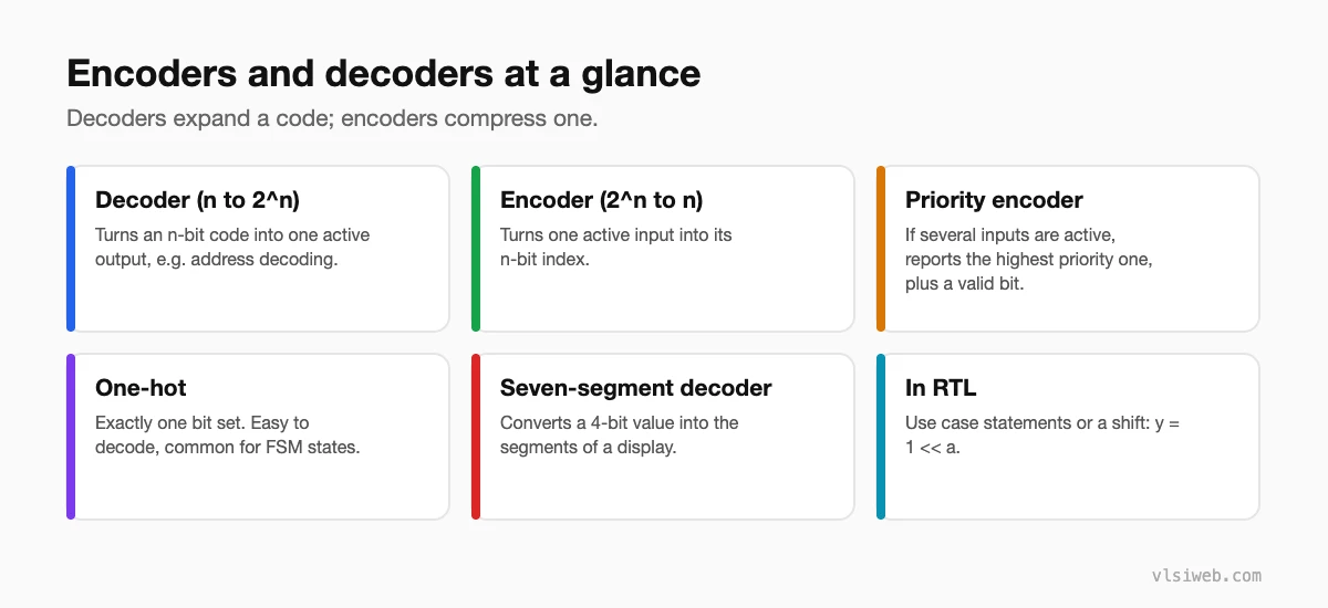
The short answer: a decoder turns an n-bit code into one active output out of 2^n (for example, a 2-to-4 decoder). An encoder does the reverse, turning one active input into its binary index. Because real inputs can have several bits active at once, practical designs use a priority encoder, which reports the highest-priority active input plus a valid flag.
This post combines my older posts on encoders and decoders, with Verilog for each.
- At a glance
- Decoders
- Encoders and priority encoders
- One-hot encoding
Table of Contents
Part 1: At a glance
Part 2: Decoders
| A1 | A0 | Y3 | Y2 | Y1 | Y0 |
|---|---|---|---|---|---|
| 0 | 0 | 0 | 0 | 0 | 1 |
| 0 | 1 | 0 | 0 | 1 | 0 |
| 1 | 0 | 0 | 1 | 0 | 0 |
| 1 | 1 | 1 | 0 | 0 | 0 |
module dec2to4 (
  input  wire [1:0] a,
  input  wire       en,
  output wire [3:0] y
);
  assign y = en ? (4'b0001 << a) : 4'b0000;
endmodule
Decoders are used for address decoding (selecting which memory or register responds), driving one-hot control signals and seven-segment displays.
Part 3: Encoders and priority encoders
A plain 4-to-2 encoder assumes exactly one input is active. If two are active, its output is meaningless. A priority encoder fixes that by giving one input priority:
module prio_enc4 (
  input  wire [3:0] req,
  output reg  [1:0] idx,
  output wire       valid
);
  assign valid = |req;
  always @(*) begin
    casez (req)
      4'b1???: idx = 2'd3;   // highest priority
      4'b01??: idx = 2'd2;
      4'b001?: idx = 2'd1;
      default: idx = 2'd0;
    endcase
  end
endmodule
Priority encoders are used in interrupt controllers, arbiters and leading-zero counters.
Part 4: One-hot encoding
One-hot codes have exactly one bit set. They are easy to decode (each bit is already a select line), which is why FSMs, especially on FPGAs, often use one-hot state encoding. The cost is more flops than a binary encoding.
Practise this on VLSI Forge
I built VLSI Forge so you can write RTL in your browser, run it on a real simulator and check every signal in the waveform. Free, nothing to install.
FAQ
What is the difference between an encoder and a decoder?
A decoder expands an n-bit code into 2^n lines; an encoder compresses 2^n lines into an n-bit code.
Why use a priority encoder?
Because in real designs several inputs can be active at once, and a plain encoder gives a wrong answer in that case.
What does the valid output of a priority encoder mean?
That at least one input is active. Without it, “no input active” and “input 0 active” look the same.
Is casez safe to use for synthesis?
Yes, casez with ? wildcards is a standard and synthesisable way to write priority logic.
