


The short answer: a multiplexer (mux) selects one of several inputs and passes it to a single output, controlled by select lines: a 2^n:1 mux has n select lines. A demultiplexer does the reverse, routing one input to one of several outputs. Muxes are everywhere in digital design, from datapath selection to building any logic function from a truth table.
This post combines my older posts on multiplexers, demultiplexers and using a mux as a universal circuit.
- Key facts
- The 4:1 multiplexer
- A mux as a universal logic block
- Demultiplexers
- Design notes
Table of Contents
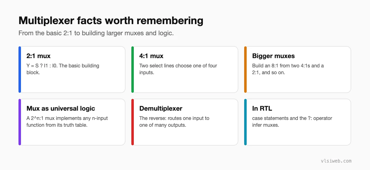
Part 1: Key facts
Part 2: The 4:1 multiplexer
| S1 | S0 | Y |
|---|---|---|
| 0 | 0 | I0 |
| 0 | 1 | I1 |
| 1 | 0 | I2 |
| 1 | 1 | I3 |
module mux4 #(parameter W = 8) (
  input  wire [W-1:0] i0, i1, i2, i3,
  input  wire [1:0]   s,
  output reg  [W-1:0] y
);
  always @(*) begin
    case (s)
      2'd0: y = i0;
      2'd1: y = i1;
      2'd2: y = i2;
      default: y = i3;
    endcase
  end
endmodule
Part 3: A mux as a universal logic block
Any n-input function can be built from a 2^n:1 mux: connect the inputs to the select lines and tie each data input to the function’s output for that combination. For example, a 4:1 mux with A and B on the selects and data inputs 0, 1, 1, 0 implements A XOR B. With a trick (feeding the last variable or its complement into the data inputs), a 2^(n-1):1 mux is enough. This is exactly how FPGA lookup tables work.
Part 4: Demultiplexers
A 1:4 demux sends its input to the output selected by S1 and S0, with the others held at 0. A decoder with an enable input behaves exactly like a demux, which is why the two are often treated as the same block.
module demux4 (
  input  wire       d,
  input  wire [1:0] s,
  output wire [3:0] y
);
  assign y = d ? (4'b0001 << s) : 4'b0000;
endmodule
Part 5: Design notes
- Large muxes with many inputs become deep logic and can limit timing; consider pipelining or one-hot selects.
- A case statement without a default, or an if without an else, in a combinational block creates a latch.
- Clock muxes are special: use glitch-free clock switching cells, never a plain mux.
Practise this on VLSI Forge
I built VLSI Forge so you can write RTL in your browser, run it on a real simulator and check every signal in the waveform. Free, nothing to install.
FAQ
How many select lines does an 8:1 mux need?
Three, since 2^3 = 8.
Why are FPGA LUTs related to muxes?
A LUT is essentially a small memory feeding a mux whose select lines are the logic inputs, so it can implement any function of those inputs.
What is the difference between a demux and a decoder?
A decoder activates one output based on a code; a demux routes a data input to one output. A decoder with an enable is effectively a demux.
Does the ?: operator create a mux?
Yes. a = s ? x : y synthesises to a 2:1 multiplexer.
