


The short answer: a register is a group of flip-flops that store a multi-bit value on the same clock edge, usually with an enable. A shift register moves its bits one position on every clock edge. Shift registers come in four flavours (SISO, SIPO, PISO and PIPO) and are used for serial-to-parallel conversion, delays, LFSRs and the scan chains used to test chips.
Registers are the simplest sequential block, but they show up everywhere, from pipeline stages to SPI and UART interfaces.
- A shift register
- Types of shift register
- Verilog examples
- Where registers and shift registers are used
Table of Contents
Part 1: A shift register
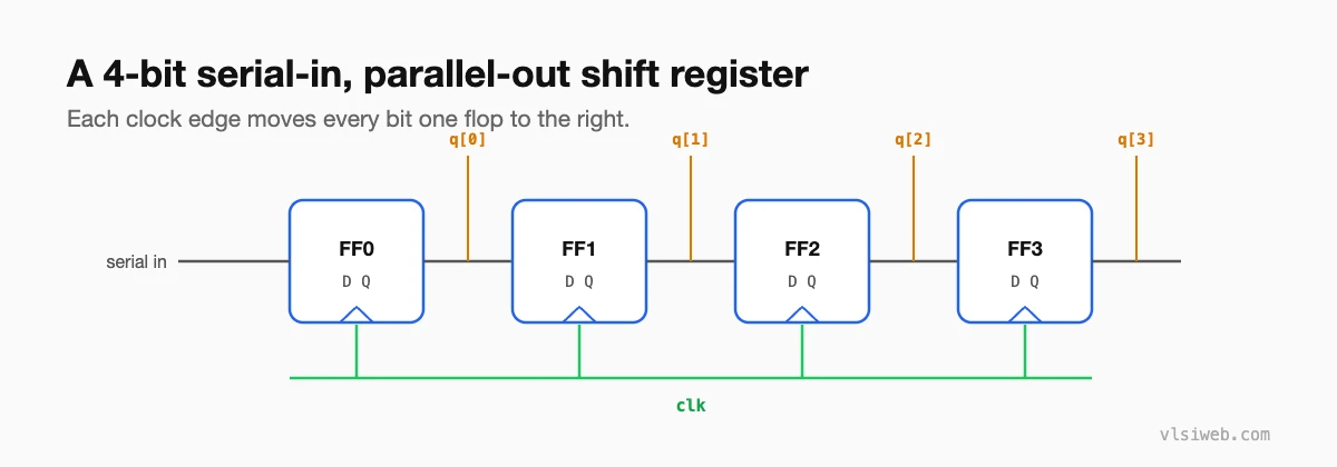
Part 2: Types of shift register
| Type | In | Out | Typical use |
|---|---|---|---|
| SISO | Serial | Serial | Delay lines |
| SIPO | Serial | Parallel | Receiving serial data (UART, SPI) |
| PISO | Parallel | Serial | Sending serial data |
| PIPO | Parallel | Parallel | Plain register with load |
Part 3: Verilog examples
// Register with enable
always @(posedge clk or negedge rst_n)
  if (!rst_n)  q <= '0;
  else if (en) q <= d;

// 8-bit SIPO shift register (shifts in at the LSB)
always @(posedge clk or negedge rst_n)
  if (!rst_n)     sr <= 8'h00;
  else if (shift) sr <= {sr[6:0], serial_in};

// 8-bit LFSR (Fibonacci), taps for x^8 + x^6 + x^5 + x^4 + 1
always @(posedge clk or negedge rst_n)
  if (!rst_n) lfsr <= 8'h01;   // must not be all zeros
  else        lfsr <= {lfsr[6:0], lfsr[7] ^ lfsr[5] ^ lfsr[4] ^ lfsr[3]};
Part 4: Where registers and shift registers are used
- Pipeline registers between stages of a datapath.
- Serial interfaces: UART, SPI and I2C use PISO to send and SIPO to receive.
- LFSRs for pseudo-random sequences, CRC and built-in self-test.
- Scan chains: in test mode, every flop in a chip is linked into giant shift registers so testers can load and read internal state. See what a DFT engineer does.
Practise this on VLSI Forge
I built VLSI Forge so you can write RTL in your browser, run it on a real simulator and check every signal in the waveform. Free, nothing to install.
Shift register and serial interface problems
FAQ
What is the difference between a register and a shift register?
A register loads all its bits at once; a shift register moves bits along one position per clock.
Why must an LFSR not start at all zeros?
For an XOR-based LFSR, all zeros maps to all zeros, so it would stay stuck there forever.
How long does a SIPO take to receive N bits?
N clock cycles, one bit per shift.
What is a barrel shifter?
A combinational circuit that shifts or rotates a word by any amount in a single cycle, unlike a shift register which moves one position per clock.
