

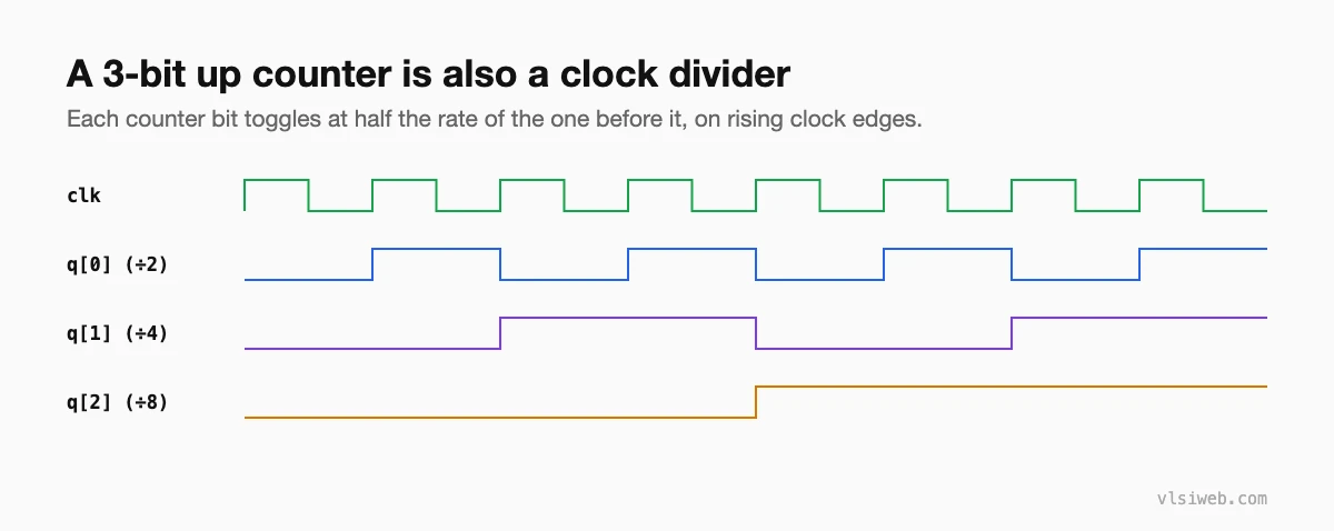
The short answer: a counter is a register that steps through a sequence of values on each clock edge: up, down, modulo-N, ring or Johnson. Each bit of a binary up counter toggles at half the rate of the one below it, so counters are also the basis of clock dividers. In real chips, though, it is usually better to generate a clock enable than a divided clock.
This post combines my older posts on counters and clock dividers.
- Counters as clock dividers
- Types of counters
- Verilog: a modulo-N counter
- Clock dividers, done safely
- Ripple vs synchronous counters
Table of Contents
Part 1: Counters as clock dividers
Part 2: Types of counters
| Counter | Sequence (4-bit) | Notes |
|---|---|---|
| Binary up | 0, 1, 2, … 15, 0 | The default; adder plus register |
| Modulo-N | 0 … N-1, 0 | Compare and wrap, e.g. a BCD counter (N = 10) |
| Up/down | Either direction | Controlled by a direction input |
| Ring | 0001, 0010, 0100, 1000 | One-hot; N states with N flops |
| Johnson | 0000, 0001, 0011, 0111, 1111, 1110, … | 2N states with N flops |
| Gray | One bit changes per step | Used for pointers crossing clock domains |
Part 3: Verilog: a modulo-N counter
module mod_n_counter #(parameter N = 10, W = 4) (
  input  wire         clk, rst_n, en,
  output reg  [W-1:0] count,
  output wire         wrap        // high on the last count
);
  assign wrap = en && (count == N-1);

  always @(posedge clk or negedge rst_n)
    if (!rst_n)    count <= {W{1'b0}};
    else if (wrap) count <= {W{1'b0}};
    else if (en)   count <= count + 1'b1;
endmodule
Part 4: Clock dividers, done safely
A divide-by-2 is just a flop that toggles every cycle. Odd divisions with a 50% duty cycle (divide-by-3, by-5) need logic on both clock edges. But generating new clocks from logic creates extra clock domains, skew and timing headaches.
My advice: in ASIC and FPGA RTL, prefer a clock enable. Keep everything on the original clock and use the counter’s wrap pulse as an enable for the slower logic. Real divided clocks should come from PLLs or dedicated clock-generation cells and be properly constrained.
Part 5: Ripple vs synchronous counters
A ripple (asynchronous) counter clocks each flop from the previous flop’s output. It is small, but each bit changes at a slightly different time, so the outputs glitch through invalid values. Synchronous counters, where every flop shares the same clock, are the standard in modern designs.
Practise this on VLSI Forge
I built VLSI Forge so you can write RTL in your browser, run it on a real simulator and check every signal in the waveform. Free, nothing to install.
FAQ
How many flops does a modulo-10 counter need?
Four, because 2^3 = 8 is too few and 2^4 = 16 is enough.
How do I make a divide-by-3 clock with 50% duty cycle?
Use a modulo-3 counter and combine flops clocked on the rising and falling edges. In most RTL, though, a clock enable is the better solution.
What is a Johnson counter used for?
Generating multi-phase timing signals; it gives 2N states from N flops and decodes easily.
Why avoid ripple counters?
Their outputs change at different times, causing glitches, and each stage adds a new clock domain for timing analysis.
