

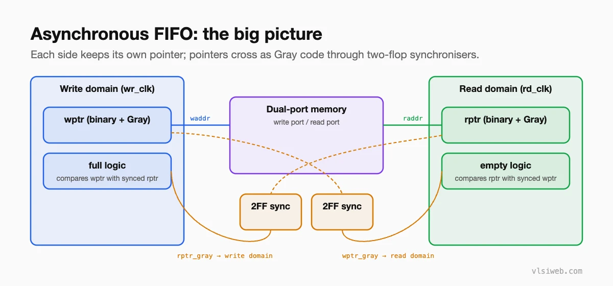
The short answer: an asynchronous FIFO lets one clock domain write data and another read it, safely and at full speed. Each side keeps its own binary pointer, converts it to Gray code, and sends that Gray pointer across through a two-flop synchroniser. The write side compares its pointer with the synchronised read pointer to detect full; the read side does the opposite to detect empty. Gray code makes this safe, because only one bit changes per increment.
If you only learn one CDC structure in depth, make it this one. Async FIFOs are everywhere: between a CPU and a bus, between a network interface and the core, between any two blocks running on different clocks. And they come up in almost every RTL design interview.
- The big picture
- Why Gray code
- Full and empty
- Verilog
- Mistakes I would watch for
Table of Contents
Part 1: The big picture
Part 2: Why Gray code
A binary counter can change many bits at once (for example 0111 to 1000). If the read side samples the write pointer during that change, each bit may resolve differently and it could see any value at all. In Gray code, consecutive values differ in exactly one bit, so a sample taken mid-change gives either the old or the new value. Both are safe: at worst the FIFO looks slightly more full or more empty than it really is, for a cycle or two.
This only works if the pointer increments by one at a time and the Gray value is driven straight from a flop. That is also why async FIFO depths are normally a power of two.
Part 3: Full and empty
- Pointers are one bit wider than the address, so you can tell a full FIFO from an empty one.
- Empty (read side): the next read Gray pointer equals the synchronised write Gray pointer.
- Full (write side): the next write Gray pointer equals the synchronised read Gray pointer with its two most significant bits inverted. That is the Gray-code form of “same address, different wrap bit”.
- Both flags are pessimistic because of the synchroniser delay: full and empty clear a couple of cycles late, which is safe.
Part 4: Verilog
module async_fifo #(
  parameter DW = 8,               // data width
  parameter AW = 4                // address width: depth = 2**AW
)(
  input  wire          wclk, wrst_n, winc,
  input  wire [DW-1:0] wdata,
  output reg           wfull,
  input  wire          rclk, rrst_n, rinc,
  output wire [DW-1:0] rdata,
  output reg           rempty
);
  reg [DW-1:0] mem [0:(1<<AW)-1];

  reg [AW:0] wbin, wgray, rbin, rgray;
  reg [AW:0] wq1_rgray, wq2_rgray;   // read pointer synced into wclk
  reg [AW:0] rq1_wgray, rq2_wgray;   // write pointer synced into rclk

  // ---------------- write domain ----------------
  wire [AW:0] wbin_next  = wbin + {{AW{1'b0}}, (winc & ~wfull)};
  wire [AW:0] wgray_next = (wbin_next >> 1) ^ wbin_next;

  always @(posedge wclk)
    if (winc & ~wfull) mem[wbin[AW-1:0]] <= wdata;

  always @(posedge wclk or negedge wrst_n)
    if (!wrst_n) begin
      wbin <= 0; wgray <= 0; wq1_rgray <= 0; wq2_rgray <= 0; wfull <= 1'b0;
    end else begin
      wbin      <= wbin_next;
      wgray     <= wgray_next;
      wq1_rgray <= rgray;
      wq2_rgray <= wq1_rgray;
      wfull     <= (wgray_next == {~wq2_rgray[AW:AW-1], wq2_rgray[AW-2:0]});
    end

  // ---------------- read domain -----------------
  wire [AW:0] rbin_next  = rbin + {{AW{1'b0}}, (rinc & ~rempty)};
  wire [AW:0] rgray_next = (rbin_next >> 1) ^ rbin_next;

  assign rdata = mem[rbin[AW-1:0]];

  always @(posedge rclk or negedge rrst_n)
    if (!rrst_n) begin
      rbin <= 0; rgray <= 0; rq1_wgray <= 0; rq2_wgray <= 0; rempty <= 1'b1;
    end else begin
      rbin      <= rbin_next;
      rgray     <= rgray_next;
      rq1_wgray <= wgray;
      rq2_wgray <= rq1_wgray;
      rempty    <= (rgray_next == rq2_wgray);
    end
endmodule
This is the classic structure popularised by Clifford Cummings’ papers on asynchronous FIFO design, which I would recommend reading next. The read data here comes straight from the memory (first-word fall-through); many designs register it instead.
Part 5: Mistakes I would watch for
- Synchronising the binary pointer instead of the Gray pointer.
- Generating the Gray pointer with combinational logic after the flop, so it can glitch at the crossing.
- Forgetting to constrain the pointer crossing in STA: the Gray bits should arrive within roughly one destination clock period of each other.
- Using a non-power-of-two depth without a special Gray scheme.
- Resetting the two sides at different times without thinking about what the other side sees. See reset domain crossing.
Practise this on VLSI Forge
I built VLSI Forge so you can write RTL in your browser, run it on a real simulator and check every signal in the waveform. Free, nothing to install.
CDC and RDC problems · RTL Design problems
Next, see how to calculate FIFO depth for a given burst and clock ratio.
FAQ
Why is the pointer one bit wider than the address?
So the FIFO can tell full from empty. When the addresses match, the extra wrap bit says whether the writer is a whole lap ahead (full) or level (empty).
Why are full and empty “pessimistic”?
Each side sees the other’s pointer two cycles late, so it may think the FIFO is fuller or emptier than it really is. That only costs a little throughput; it never causes overflow or underflow.
Can an async FIFO have a non-power-of-two depth?
Yes, but it needs a special Gray code sequence that still changes one bit at a time when it wraps. Power-of-two depths are much simpler.
Is an async FIFO needed if the clocks have the same frequency?
Yes, if they come from different sources. Their phases drift, so the crossing is still asynchronous.
