

The short answer: a handshake synchroniser moves a multi-bit value between clock domains safely. The source puts the data on a bus and holds it stable, then raises a request. The request is synchronised into the destination, which samples the now-stable data and raises an acknowledge. The acknowledge is synchronised back to the source, which only then changes the data. It is simple and robust, but slow, so it suits occasional transfers rather than data streams.
Handshakes are the go-to answer when you need to send a configuration word, a status value or an occasional command across a clock boundary. They are also a favourite interview topic. Here is how they work, with Verilog you can use.
- Why a handshake is needed
- The four-phase handshake
- Verilog example
- Two-phase vs four-phase
- When to use something else
Table of Contents
Part 1: Why a handshake is needed
You cannot synchronise a multi-bit bus bit by bit, because each bit may resolve on a different cycle and the destination may see a value that was never sent. The handshake avoids this by keeping the data completely stable while it is sampled, and synchronising only single-bit control signals (req and ack). See the CDC guide for the basics of synchronisers.
Part 2: The four-phase handshake
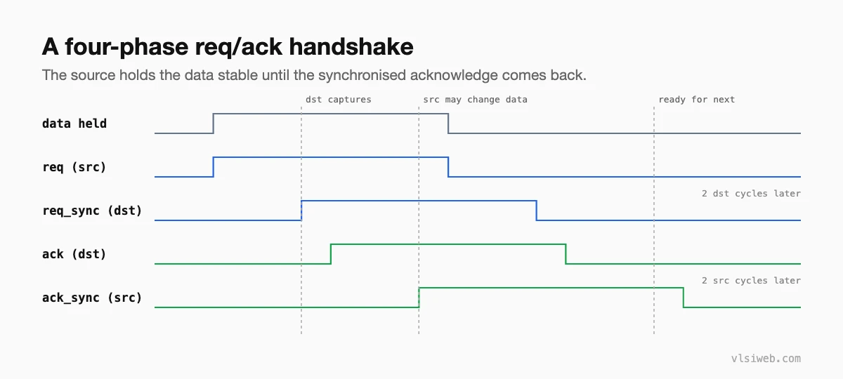
- Source drives the data and raises
req. - Destination sees
req_sync, captures the data (it has been stable for at least two cycles), and raisesack. - Source sees
ack_sync, dropsreqand may now change the data. - Destination sees
reqdrop and dropsack. When the source seesack_synclow, it can start the next transfer.
Part 3: Verilog example
// Source side (clk_a): send one word per handshake
module hs_src #(parameter W = 8) (
  input  wire         clk_a, rst_a_n,
  input  wire         send,        // request to send data_in
  input  wire [W-1:0] data_in,
  input  wire         ack_async,   // from destination
  output reg  [W-1:0] data_bus,    // held stable while req is high
  output reg          req,
  output wire         busy
);
  reg ack_s1, ack_s2;
  always @(posedge clk_a or negedge rst_a_n)
    if (!rst_a_n) {ack_s2, ack_s1} <= 2'b00;
    else          {ack_s2, ack_s1} <= {ack_s1, ack_async};

  assign busy = req | ack_s2;

  always @(posedge clk_a or negedge rst_a_n)
    if (!rst_a_n) begin
      req <= 1'b0; data_bus <= {W{1'b0}};
    end else if (!busy && send) begin
      data_bus <= data_in;          // load, then raise req
      req      <= 1'b1;
    end else if (req && ack_s2) begin
      req      <= 1'b0;             // ack seen: release
    end
endmodule

// Destination side (clk_b)
module hs_dst #(parameter W = 8) (
  input  wire         clk_b, rst_b_n,
  input  wire         req_async,
  input  wire [W-1:0] data_bus,
  output reg          ack,
  output reg  [W-1:0] data_out,
  output reg          valid        // one-cycle pulse in clk_b
);
  reg req_s1, req_s2;
  always @(posedge clk_b or negedge rst_b_n)
    if (!rst_b_n) {req_s2, req_s1} <= 2'b00;
    else          {req_s2, req_s1} <= {req_s1, req_async};

  always @(posedge clk_b or negedge rst_b_n)
    if (!rst_b_n) begin
      ack <= 1'b0; valid <= 1'b0; data_out <= {W{1'b0}};
    end else begin
      valid <= 1'b0;
      if (req_s2 && !ack) begin
        data_out <= data_bus;       // stable: safe to sample
        ack      <= 1'b1;
        valid    <= 1'b1;
      end else if (!req_s2 && ack) begin
        ack <= 1'b0;
      end
    end
endmodule
Notice that data_bus is loaded one cycle before or together with req rising, and never changes while req or the synchronised ack is high.
Part 4: Two-phase vs four-phase
| Four-phase (return to zero) | Two-phase (toggle) | |
|---|---|---|
| Signalling | req and ack go high, then low | each transfer toggles req and ack once |
| Speed | Slower: four synchronisation trips | Faster: two trips per transfer |
| Logic | Simpler to understand and verify | Needs edge detection on both sides |
Four-phase is the more common choice when transfers are rare and simplicity matters most.
Part 5: When to use something else
- For a continuous stream of data, use an asynchronous FIFO instead; a handshake takes several cycles per word.
- For a single control bit, a two-flop or toggle synchroniser is enough.
- For counters, use Gray code.
Practise this on VLSI Forge
I built VLSI Forge so you can write RTL in your browser, run it on a real simulator and check every signal in the waveform. Free, nothing to install.
FAQ
How many cycles does a four-phase handshake take?
Roughly four synchronisation delays (about two destination plus two source cycles each way), so typically around 8 to 10 cycles in total, depending on the clocks.
Why must data be stable before req rises?
Because the destination samples the data as soon as it sees the synchronised request. If the data changes then, the destination could capture a mix of old and new bits.
Is a handshake the same as valid/ready?
No. Valid/ready is a flow-control protocol within one clock domain. A CDC handshake synchronises req and ack between two unrelated clocks.
How do I verify a handshake?
Add assertions that the data bus never changes while req is high or ack has not returned, and run structural CDC checks to confirm req and ack are properly synchronised.
