


The short answer: In Verilog, a flip-flop is an always block triggered on a clock edge with non-blocking assignments: always @(posedge clk) q <= d;. Add the reset to the sensitivity list for an asynchronous reset, or test it inside the block for a synchronous one. Registers are just groups of flip-flops, shift registers and counters are registers with next-state logic, and a latch is a level-sensitive block (if (en) q = d;) that you should only write deliberately.
Almost every sequential design is built from the same few templates. In this post I collect the ones I use: flip-flops with different resets and enables, latches, registers, shift registers and counters. It replaces three older posts on flip-flops and latches, registers and counters.
For the theory behind them (setup and hold, latch vs flip-flop behaviour), see my latches vs flip-flops and counters posts in Digital Circuits.
- D flip-flop templates
- Asynchronous or synchronous reset?
- Latches (on purpose only)
- Registers and shift registers
- Counters
- Rules for sequential blocks
Table of Contents
Part 1: D flip-flop templates
// no reset (fine for datapath registers that are always written before use)
always @(posedge clk)
  q <= d;

// asynchronous active-low reset
always @(posedge clk or negedge rst_n)
  if (!rst_n) q <= 1'b0;
  else        q <= d;

// synchronous active-high reset
always @(posedge clk)
  if (rst) q <= 1'b0;
  else     q <= d;

// with clock enable
always @(posedge clk or negedge rst_n)
  if (!rst_n)  q <= 1'b0;
  else if (en) q <= d;      // no else: q keeps its value
Part 2: Asynchronous or synchronous reset?
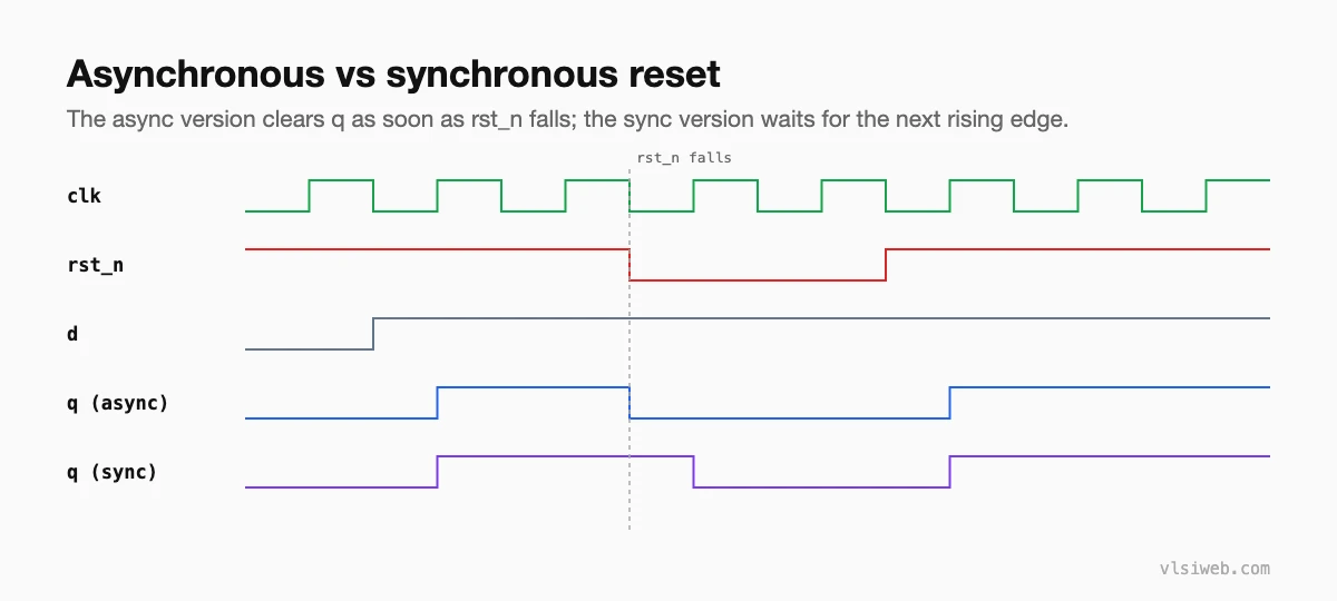
| Asynchronous | Synchronous | |
|---|---|---|
| Acts | Immediately | At the next clock edge |
| Needs a running clock | No | Yes |
| Reset path timing | Recovery and removal checks | Normal setup and hold |
| Common risk | Release near a clock edge | Reset pulse shorter than a clock period is missed |
Many teams use asynchronous assertion with synchronous release: the reset clears flops immediately, but is released through a reset synchroniser so all flops leave reset on the same edge. Whatever you choose, use one style consistently.
Part 3: Latches (on purpose only)
always @(*)
  if (en) q = d;     // transparent while en = 1, holds while en = 0
ASIC designs rarely use latches, except in clock gating cells and some high-performance designs that use time borrowing. If synthesis reports a latch you didn’t mean, it’s a bug. See writing combinational logic.
Part 4: Registers and shift registers
// N-bit register with load
always @(posedge clk or negedge rst_n)
  if (!rst_n)    r <= {N{1'b0}};
  else if (load) r <= din;

// serial-in, parallel-out shift register
always @(posedge clk)
  if (shift_en) sr <= {sr[N-2:0], sin};

// pipeline: three stages, one per clock
always @(posedge clk) begin
  s1 <= in;
  s2 <= s1;
  s3 <= s2;
end
Part 5: Counters
// up counter with enable and synchronous clear
always @(posedge clk or negedge rst_n)
  if (!rst_n)      cnt <= 0;
  else if (clr)    cnt <= 0;
  else if (en)     cnt <= cnt + 1'b1;

// modulo-N counter with terminal count
always @(posedge clk or negedge rst_n)
  if (!rst_n)      cnt <= 0;
  else if (en)     cnt <= (cnt == N-1) ? 0 : cnt + 1'b1;
assign tc = en && (cnt == N-1);

// up/down counter
always @(posedge clk)
  if (en) cnt <= up ? cnt + 1'b1 : cnt - 1'b1;
For a clock divider, I’d use a counter to make a one-cycle enable pulse rather than a new clock. Divided clocks need their own constraints and clock tree; enables don’t.
Part 6: Rules for sequential blocks
- Non-blocking assignments (<=) only.
- Only the clock and an asynchronous reset in the sensitivity list.
- The reset branch comes first and only assigns reset values.
- Decide which registers really need a reset; large datapaths often don’t, which saves area and power.
- One register is written by exactly one always block.
Practise this on VLSI Forge
I built VLSI Forge so you can write RTL in your browser, run it on a real simulator and check every signal in the waveform. Free, nothing to install.
Previous in my Verilog series: Writing combinational logic. Next: FSMs in Verilog.
FAQ
How do I write a D flip-flop in Verilog?
always @(posedge clk) q <= d; Add or negedge rst_n to the sensitivity list for an asynchronous active-low reset.
How do I write a latch in Verilog?
always @(*) if (en) q = d; with no else. Only write latches when you really mean to.
What is the difference between synchronous and asynchronous reset?
A synchronous reset acts on the clock edge; an asynchronous reset acts immediately, without a clock.
Should every flip-flop have a reset?
Control logic and FSM state, yes. Datapath registers that are always written before they’re read often don’t need one.
