

The short answer: STA interviews always start with setup and hold: the equations, how to calculate slack, and how to fix violations. Then they move to clocks (skew, latency, jitter, uncertainty), SDC constraints (clocks, input and output delays, false and multicycle paths), and sign-off topics like corners, OCV and derates, CRPR, crosstalk and PBA vs GBA. Practise the calculations on paper; most interviews include at least one.
Static timing analysis is the one topic that physical design, STA, synthesis and even RTL engineers all get asked about. The questions look simple, but interviewers follow up until they find the edge of your understanding, so I’ve focused on getting the reasoning right, not on listing every command.
If you’re new to the role itself, my post on the STA engineer role explains what the job involves day to day.
- Setup and hold
- Clocks
- SDC constraints
- Sign-off topics
Table of Contents
Part 1: Setup and hold
1. What is static timing analysis, and how is it different from timing simulation?
STA checks every timing path in the design against the constraints, without any test vectors, using worst-case and best-case delays. Timing simulation only checks the paths your stimulus happens to exercise. STA is exhaustive and fast, but it relies entirely on correct constraints.
2. What are the four kinds of timing paths?
Input to register, register to register, register to output, and input to output (pure combinational). Each path starts at a startpoint (an input port or a flop clock pin) and ends at an endpoint (an output port or a flop data pin).
3. Write the setup and hold checks.
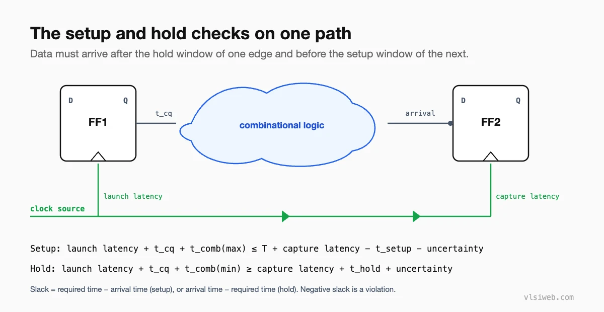
Using the picture above, with arrival = launch latency + tcq + tcomb:
- Setup: arrival(max) ≤ T + capture latency − tsetup − setup uncertainty
- Hold: arrival(min) ≥ capture latency + thold + hold uncertainty
Setup checks against the next clock edge; hold checks against the same edge.
4. Calculate the slack for this path.
Clock period 10 ns, tcq 1 ns, max logic delay 6 ns, setup 0.5 ns, capture clock 0.5 ns later than launch, setup uncertainty 0.3 ns.
required = 10 + 0.5 - 0.5 - 0.3 = 9.7 ns
arrival  = 1 + 6             = 7.0 ns
setup slack = 9.7 - 7.0      = +2.7 ns  (met)
For hold, with min logic delay 0.2 ns, hold time 0.3 ns and hold uncertainty 0.1 ns: arrival = 1.2 ns, required = 0.5 + 0.3 + 0.1 = 0.9 ns, hold slack = +0.3 ns.
5. Why is hold independent of the clock frequency?
Both sides of the hold check refer to the same clock edge, so the period never appears in the equation. That’s also why a hold violation in silicon can’t be fixed by slowing the clock.
6. How do you fix a setup violation?
- Upsize cells or swap to a lower-Vt (faster) cell.
- Restructure logic or move logic to a less critical stage.
- Fix long wires with buffering or better placement.
- Use useful skew: delay the capture clock a little.
- As a last resort, pipeline the path or relax the frequency.
7. How do you fix a hold violation?
Add delay on the data path: delay buffers, downsized or higher-Vt cells, or longer routing. Fix it in the corner where hold is worst (usually fast), and make sure the added delay doesn’t create a setup violation in the slow corner.
Part 2: Clocks
8. What are clock latency, skew, jitter and uncertainty?
Latency is the delay from the clock source to a flop’s clock pin (source latency plus network latency). Skew is the difference in latency between two flops. Jitter is the cycle-to-cycle variation of the clock edge itself. Uncertainty is a margin you set in SDC to cover jitter, and before CTS, the expected skew.
9. Does skew help or hurt timing?
If the capture clock arrives later than the launch clock (positive skew), setup gets easier and hold gets harder. Negative skew is the opposite. Useful skew deliberately adjusts clock arrival to borrow time for critical paths.
10. What is a generated clock, and why define it?
A clock derived from another clock inside the design, for example by a divider or a clock mux. create_generated_clock tells STA its relationship to the master clock, so latency is traced through the source and paths between the two clocks are timed correctly.
11. What is a clock gating check?
When a clock passes through a gate like an AND, the enable must be stable while the clock is high (for an AND) so the gate doesn’t chop or glitch the clock. STA checks setup and hold on the enable relative to the clock at that gate. Integrated clock gating cells solve this with a latch on the enable.
12. How does a half-cycle path affect timing?
If data is launched on a rising edge and captured on a falling edge, setup only has half a period, so these paths are often critical. Hold gets an extra half period of margin.
Part 3: SDC constraints
13. What do set_input_delay and set_output_delay mean?
They describe the timing outside the block. set_input_delay says how long after the clock edge the data arrives at the input port, so the remaining time is available inside. set_output_delay says how much of the next cycle the external logic needs, so the output must be ready that much earlier.
14. What is the difference between a false path and a multicycle path?
A false path is never timed, because it can’t happen functionally or doesn’t matter (for example, between asynchronous clocks or from a static configuration register). A multicycle path is still timed, but data is allowed more than one cycle to arrive.
15. Why do you need a hold multicycle with a setup multicycle?
set_multicycle_path 2 -setup -from [get_pins a_reg/CP] -to [get_pins b_reg/D]
set_multicycle_path 1 -hold  -from [get_pins a_reg/CP] -to [get_pins b_reg/D]
Moving the setup check to the second edge also moves the default hold check forward by one cycle, which would make hold far too strict. The -hold 1 moves it back to the original edge.
16. set_clock_groups -asynchronous or set_false_path?
Both stop STA from timing paths between the clocks. set_clock_groups is cleaner because it covers both directions and states the intent: these clocks are unrelated. It also matters for crosstalk analysis, where asynchronous clocks are treated as able to switch at any time relative to each other.
17. What are design rule constraints?
Max transition, max capacitance and max fan-out. They keep cells inside the range their timing libraries are characterised for, and fixing them comes before fixing timing.
18. What is set_case_analysis used for?
Setting a signal, such as a mode select or test-mode pin, to a constant so STA only analyses the paths active in that mode. Each functional and test mode usually gets its own analysis.
Part 4: Sign-off topics
19. Which corners do you check setup and hold in?
Classically, setup at the slow corner (slow process, low voltage, high temperature) and hold at the fast corner. At advanced nodes, temperature inversion means low temperature can be slower, so both temperature extremes are checked. In practice, sign-off runs every check across many corners and modes (MCMM).
20. What is OCV, and what are derates?
On-chip variation means identical cells on the same die have slightly different delays. STA models it by making the launch path slower and the capture path faster for setup (and the reverse for hold), using derate factors. AOCV adjusts derates by path depth and distance; POCV and LVF use statistical per-cell variation, which is less pessimistic.
21. What is CRPR?
When launch and capture clocks share part of the clock tree, OCV derates make that common part both fast and slow at once, which is impossible. Clock reconvergence pessimism removal adds back the difference for the shared part.
22. How does crosstalk affect timing?
When a neighbouring wire (the aggressor) switches in the opposite direction to the victim, it slows the victim, hurting setup; switching in the same direction speeds it up, hurting hold. Crosstalk can also inject glitches on quiet nets. Fixes include spacing, shielding, upsizing the victim driver and reducing aggressor slew.
23. What is the difference between GBA and PBA?
Graph-based analysis uses the worst slew at each node for every path through it, which is fast but pessimistic. Path-based analysis recalculates each path with its own real slews, which removes pessimism and is used to recover violations near sign-off.
24. How does latch timing work?
A latch is transparent for part of the cycle, so data arriving late can still pass through while it’s open. STA lets the path “borrow” time from the next stage, up to the latch’s closing edge. Time borrowing helps balance pipeline stages but makes analysis harder.
25. What are recovery and removal checks?
Setup and hold-like checks for asynchronous reset release: reset must de-assert at least the recovery time before the clock edge and not within the removal time after it.
Practise this on VLSI Forge
I built VLSI Forge so you can write RTL in your browser, run it on a real simulator and check every signal in the waveform. Free, nothing to install.
FAQ
Do I need to know a specific STA tool?
Knowing one (PrimeTime or Tempus) helps, but interviewers care far more about concepts and SDC. Commands are easy to learn on the job.
What calculation should I practise most?
Setup and hold slack with skew and uncertainty, and the effect of a multicycle path. Do a few by hand until it’s automatic.
Are STA questions asked for RTL roles?
Yes, usually setup and hold, skew, false and multicycle paths, and how to fix a long path in RTL by pipelining or restructuring.
How do I explain OCV simply?
Same cell, slightly different speed in different places on the chip, so STA assumes the worst combination for each check.
