

The short answer: CDC (clock domain crossing) questions test whether you can move signals safely between unrelated clocks: metastability, two-flop synchronisers, pulse and multi-bit crossings, handshakes and asynchronous FIFOs with Gray-coded pointers. RDC (reset domain crossing) questions test the same thinking for resets: why reset release must be synchronised, and what goes wrong when a flop in one reset domain feeds a flop in another. The key skill is matching the right technique to each kind of signal.
CDC bugs are some of the most expensive in the industry, because they often pass every simulation and only show up in silicon, randomly. That’s why interviewers for design, verification and even STA roles love these questions.
This post combines my older CDC and RDC interview posts into one. For the full explanations behind the answers, see my guides to clock domain crossing and asynchronous FIFOs.
- CDC fundamentals
- Crossing techniques
- Constraints and tools
- Reset domain crossings (RDC)
Table of Contents
Part 1: CDC fundamentals
1. What is a clock domain crossing?
A path where data launched by a flop on one clock is captured by a flop on another clock that is asynchronous or has no fixed phase relationship to it. Because the capture flop can sample while the data is changing, the normal setup and hold guarantees don’t apply.
2. What is metastability, and what is MTBF?
If a flop samples while its input is changing, its output can hang between 0 and 1 for an unpredictable time before settling. We can’t prevent it on a CDC path; we can only make failures extremely rare. The mean time between failures grows exponentially with the time you give the flop to resolve:
MTBF = e^(t_resolve / tau) / (T0 * f_clk * f_data)where tau and T0 are properties of the flop. That exponential is why adding one more synchroniser stage helps so much.
3. How does a two-flop synchroniser work, and why not one flop?
The first flop may go metastable; the second flop samples it one full clock cycle later, by which time it has almost certainly resolved. With one flop, a metastable value would go straight into your logic and could be read differently by different gates. Very fast clocks or high-reliability designs use three flops.
4. What rules must a synchroniser follow?
- The source signal must come straight from a flop, with no combinational logic, so it can’t glitch.
- No logic between the synchroniser flops.
- The synchroniser flops should be placed close together, and usually use special library cells.
- Only one signal per synchroniser; don’t synchronise bits of a bus separately.
5. Why can’t you synchronise a multi-bit bus with one synchroniser per bit?
Each bit can resolve on a different destination cycle, so for a cycle or more the destination may see a mix of old and new bits: a value that never existed in the source.
6. What is the reconvergence problem?
Two signals synchronised separately and then combined in the destination can arrive one cycle apart, so the combined logic sees an illegal combination. Fix it by synchronising a single signal and deriving the others from it, or by using a handshake or FIFO.
7. Why doesn’t RTL simulation catch most CDC bugs?
Normal simulation doesn’t model metastability or the random extra cycle of delay through a synchroniser, so a design with a bad crossing usually passes. That’s why we use structural CDC tools, and some simulators offer metastability injection to randomise synchroniser delay.
Part 2: Crossing techniques
8. How do you pass a single-cycle pulse from a fast clock to a slow clock?
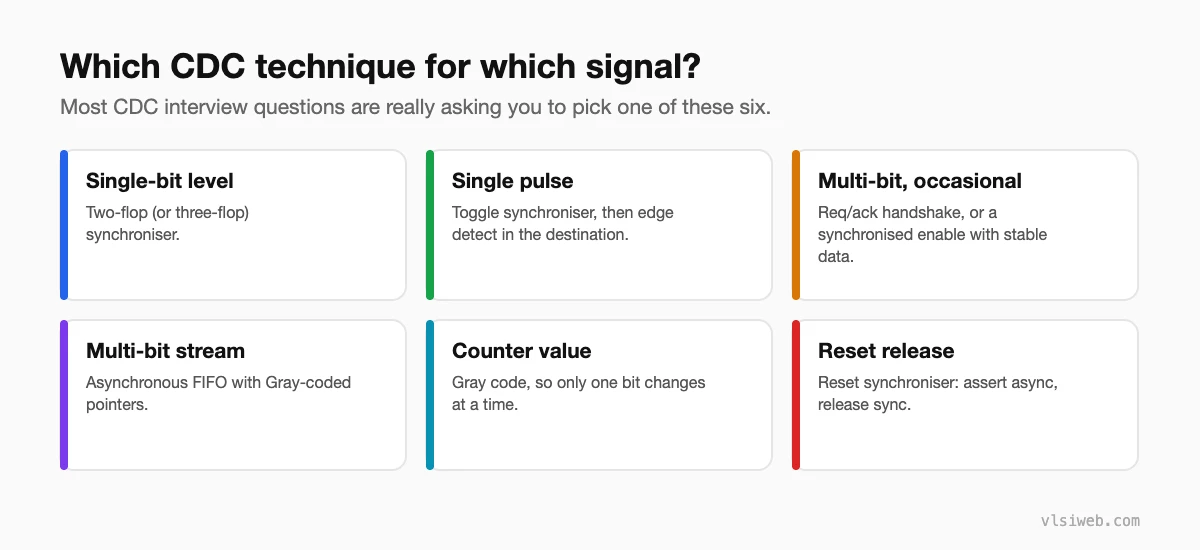
A plain synchroniser can miss it completely. Use a toggle synchroniser: turn the pulse into a level change in the source domain, synchronise the level, and detect the edge in the destination.
// source domain
always @(posedge clk_a or negedge rst_a_n)
  if (!rst_a_n)    tog <= 1'b0;
  else if (pulse_a) tog <= ~tog;

// destination domain
always @(posedge clk_b or negedge rst_b_n)
  if (!rst_b_n) s <= 3'b000;
  else          s <= {s[1:0], tog};

assign pulse_b = s[2] ^ s[1];   // one pulse per toggle
The pulses must be far enough apart (a few destination cycles), or toggles will be lost. If they can come faster, use a handshake or a FIFO.
9. And from a slow clock to a fast clock?
A pulse that lasts one slow cycle is wider than a fast cycle, so a two-flop synchroniser followed by a rising-edge detector works, as long as the fast clock is reliably faster (roughly 1.5 times or more, depending on the margin you want).
10. How does a req/ack handshake work?
The source puts data on a bus, holds it stable, and raises req. The destination synchronises req, captures the data (safe because it’s stable), and raises ack. The source synchronises ack, drops req (in a 4-phase handshake), and waits for ack to drop before sending again. It’s safe for any clock ratio, but slow: several cycles of each clock per transfer. See handshake protocols.
11. What is enable-based (mux) synchronisation?
Synchronise only a single valid or enable bit, and keep the data bus stable while it crosses. When the destination sees the synchronised enable, it loads the data through a mux. It works because the data doesn’t change while it’s sampled.
12. How does an asynchronous FIFO detect full and empty?
The read and write pointers have one extra bit (N+1 bits for a depth of 2N) and are kept in Gray code. Each pointer is synchronised into the other domain, and each flag is computed in the domain that needs it:
// read domain: empty when the pointers are equal
assign empty = (rptr_gray == wptr_gray_sync);

// write domain: full when the top two bits differ and the rest match
assign full  = (wptr_gray == {~rptr_gray_sync[N:N-1],
                               rptr_gray_sync[N-2:0]});
13. Why Gray code for the pointers?
Only one bit changes per increment, so if the destination samples during a change it sees either the old or the new pointer, never a wrong one. That only holds if the pointer moves by one at a time and the depth is a power of two.
14. Are the async FIFO’s full and empty flags exact?
No, they’re pessimistic in a safe way. Because the other pointer arrives a couple of cycles late, full and empty assert on time but de-assert a few cycles late. The FIFO never overflows or underflows; it just looks slightly fuller or emptier than it is.
15. How do you size an asynchronous FIFO?
Find the worst-case burst. Example: the writer sends 80 words back to back at 100 MHz, and the reader takes one word per cycle at 50 MHz. The burst takes 800 ns, during which the reader drains 40 words, so you need at least 80 − 40 = 40 entries. Then add a few for synchroniser latency and round up to a power of two: 64.
16. Do configuration registers need synchronisers?
Quasi-static signals, written once while the destination is idle and then left alone, are often not synchronised. That’s acceptable only if the design guarantees they’re stable before use, and the CDC tool waiver says why.
Part 3: Constraints and tools
17. How do you constrain CDC paths in STA?
Asynchronous clocks are usually declared with set_clock_groups -asynchronous, so STA doesn’t time paths between them. But some crossings still need a limit: for async FIFO Gray pointers, a set_max_delay -datapath_only of about one destination clock period keeps the bits from skewing apart. Related clocks from the same source (for example a divide-by-2) are synchronous and should be timed normally.
18. What do CDC tools check?
Structural checks: crossings with no synchroniser, combinational logic before a synchroniser, multi-bit buses synchronised bit by bit, reconvergence, and fan-out of unsynchronised signals. Many also run formal checks that handshake data really is stable. Common tools include VC SpyGlass CDC, Questa CDC and Jasper CDC. See CDC tools.
Part 4: Reset domain crossings (RDC)
19. What is a reset domain crossing?
A path from a flop with one asynchronous reset to a flop with a different reset (or no reset), even in the same clock domain. When the source reset asserts, the source output changes immediately, at any time relative to the destination clock. If the destination isn’t also in reset, it can go metastable or capture a corrupted value.
20. Why do we need a reset synchroniser?
Asserting an asynchronous reset at any time is fine. Releasing it near a clock edge isn’t: it can violate the flops’ recovery or removal time, so some flops leave reset one cycle before others, or go metastable. The standard fix asserts asynchronously and releases synchronously:
always @(posedge clk or negedge arst_n)
  if (!arst_n) {rst_n, r1} <= 2'b00;
  else         {rst_n, r1} <= {r1, 1'b1};
21. What are recovery and removal times?
They are the setup and hold equivalent for the release of an asynchronous reset: reset must be released at least the recovery time before the clock edge, and not within the removal time after it. STA checks them like setup and hold.
22. How do you fix an RDC issue?
- Reset the destination whenever the source is reset, so the glitch is never captured.
- Order the resets so the destination is held in reset first and released last.
- Gate the clock or enable of the destination while the source reset is asserted.
- Synchronise the crossing like a CDC path when none of the above is possible.
23. How do you handle reset in a design with several clocks?
One reset synchroniser per clock domain, all driven from the same asynchronous reset. If blocks must come out of reset in a set order, add a reset sequencer rather than relying on synchroniser timing.
24. Which tools check RDC?
The same families as CDC: VC SpyGlass RDC, Questa RDC and Jasper RDC, for example. They find crossings between reset domains and check ordering and isolation.
Practise this on VLSI Forge
I built VLSI Forge so you can write RTL in your browser, run it on a real simulator and check every signal in the waveform. Free, nothing to install.
FAQ
Are CDC questions only for design roles?
No. Verification engineers are asked how to verify crossings, and STA engineers how to constrain them. Everyone is expected to explain a two-flop synchroniser.
How many flops should a synchroniser have?
Two is standard. Three is used at very high clock frequencies or when reliability requirements are strict; the MTBF calculation decides.
What is the most common CDC interview question?
Async FIFO design: why Gray code, how full and empty are generated, and how to size it.
Is RDC asked as often as CDC?
Less often, but more and more, especially for SoC and low-power roles. Knowing the reset synchroniser and the basic RDC problem covers most questions.
