

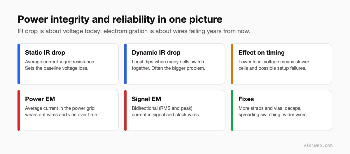
The short answer: IR drop is the supply voltage lost across the resistance of the power grid: static IR drop comes from average current, dynamic IR drop from bursts of simultaneous switching. Too much drop slows cells and can cause timing failures or functional errors. Electromigration (EM) is the gradual movement of metal atoms under high current density, which can open or short wires and vias over the chip’s lifetime. Both are checked at sign-off with tools like RedHawk or Voltus, and fixed with stronger grids, more vias, decaps, wider wires and spreading out switching activity.
A chip can meet timing on paper and still fail because its supply sags at the wrong moment, or work on day one and fail after a few years because a wire wore out. Power integrity and reliability sign-off exist to prevent both. This post replaces my older electromigration post and adds IR drop.
- The overview
- IR drop
- How IR drop affects timing
- Electromigration
- Fixing power integrity problems
Table of Contents
Part 1: The overview
Part 2: IR drop
- Static IR uses average current per cell (from power analysis) and the grid resistance. Budgets are often a few percent of the supply.
- Dynamic IR uses switching activity over time, from vectors or vectorless estimates, and includes the effect of decaps and package inductance. Clock edges, where thousands of flops switch together, are the classic hotspot.
- Hotspots usually appear far from supply pins, in dense high-activity logic, or under weak parts of the grid.
Part 3: How IR drop affects timing
Cell delay increases as local voltage drops. Sign-off flows either add voltage margin to the timing corners or run IR-aware STA, which uses the actual per-instance voltage from the IR analysis. A design that meets timing at nominal voltage but fails with real IR drop is a classic late surprise.
Part 4: Electromigration
| Type | Current | Typical concern |
|---|---|---|
| Power EM | Mostly unidirectional DC | Narrow rails and vias carrying lots of current |
| Signal EM | Bidirectional (RMS and peak) | Long, heavily loaded nets and clock nets driven by strong buffers |
The foundry gives current-density limits per layer and via, which depend on temperature and the target lifetime. Wider wires, more vias (including redundant vias) and splitting heavily loaded nets fix most violations.
Part 5: Fixing power integrity problems
- Add or widen straps, and add vias in hotspot areas.
- Add decap cells near high-activity logic.
- Spread out clock gating and switching so not everything toggles on the same edge.
- Move high-power blocks closer to supply pins or bumps.
- For EM on signals: upsize wires, add parallel routes, reduce load or drive strength.
Practise this on VLSI Forge
I built VLSI Forge so you can write RTL in your browser, run it on a real simulator and check every signal in the waveform. Free, nothing to install.
Physical Design problems · Static Timing Analysis problems
Previous in my physical design series: Sign-off timing and MCMM. Next: Physical verification.
FAQ
What is IR drop in VLSI?
The voltage lost across the resistance of the power distribution network, so cells see less than the nominal supply.
What is the difference between static and dynamic IR drop?
Static IR drop uses average current; dynamic IR drop captures local dips when many cells switch at the same time.
What is electromigration?
The gradual movement of metal atoms under high current density, which can eventually cause opens or shorts in wires and vias.
How do you fix IR drop?
Strengthen the grid with more straps and vias, add decaps, spread switching activity and place high-power logic closer to supply pins.
