

The short answer: a clock domain crossing (CDC) happens whenever a signal launched by one clock is captured by a flop on another, unrelated clock. Because the signal can change right at the capturing edge, the first flop can go metastable. Safe designs never use such a signal directly: single-bit levels go through a two-flop synchroniser, pulses through a toggle synchroniser, and multi-bit values through a handshake or an asynchronous FIFO.
CDC is one of the topics I would make sure every RTL engineer understands deeply. CDC bugs usually pass simulation, show up rarely on silicon, and are painful to debug. This guide brings together what used to be three separate posts on CDC, metastability and synchronisers, so you can learn it in one place.
- What a clock domain crossing is
- Metastability, and why it matters
- The two-flop synchroniser
- Pulses: the toggle synchroniser
- Multi-bit signals
- Rules I would always follow
Table of Contents
Part 1: What a clock domain crossing is
A clock domain is all the logic driven by one clock. Real chips have many: a CPU clock, a bus clock, memory clocks, interface clocks, always-on clocks and more. When a signal leaves one domain and is sampled in another, and the two clocks have no fixed phase relationship, you have an asynchronous crossing.
Crossings between clocks derived from the same source with a known ratio (for example a clock and its divided-by-2 version) can often be handled with normal timing analysis. The dangerous ones are crossings between truly unrelated clocks.
Part 2: Metastability, and why it matters
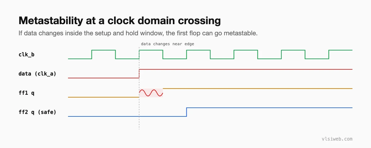
If a flop’s input changes inside its setup and hold window, the output can hang between 0 and 1 for an unpredictable time before settling. That is metastability. It always resolves eventually, but if downstream logic samples the value before it does, different flops can see different values.
The risk is measured as mean time between failures (MTBF). Roughly, MTBF grows exponentially with the time you give a metastable flop to settle, and shrinks with the clock and data rates. That is why adding one more flop of settling time makes failures astronomically rarer.
A commonly used form is:
MTBF = e^(t_r / tau) / (T0 * f_clk * f_data)

t_r    = time allowed for resolution (about one clock period)
tau    = flop resolution time constant (a process property)
T0     = a flop-specific constant
f_clk  = capturing clock frequency
f_data = rate at which the input toggles
Part 3: The two-flop synchroniser
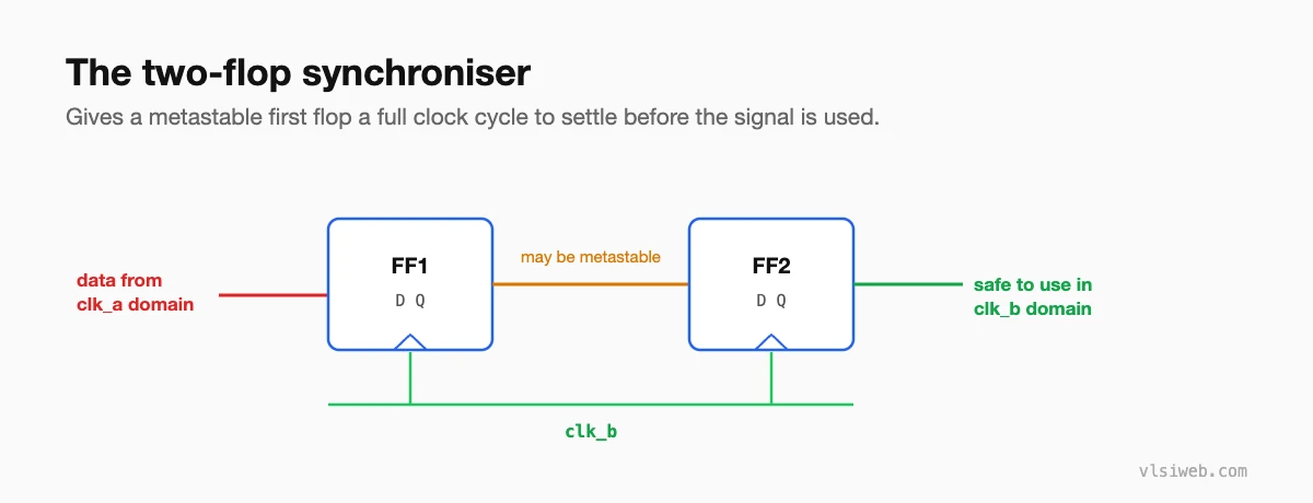
For a single-bit signal that stays stable for several destination clock cycles, two flops in the destination domain are the standard solution. Real libraries often provide a dedicated synchroniser cell with better resolution characteristics; use it if your flow has one.
module sync_2ff (
  input  wire clk_b,
  input  wire rst_b_n,
  input  wire d_async,
  output wire q_sync
);
  reg ff1, ff2;
  always @(posedge clk_b or negedge rst_b_n) begin
    if (!rst_b_n) begin
      ff1 <= 1'b0;
      ff2 <= 1'b0;
    end else begin
      ff1 <= d_async;
      ff2 <= ff1;
    end
  end
  assign q_sync = ff2;
endmodule- The input must come straight from a flop in the source domain, never from combinational logic, which can glitch.
- No logic between the two synchroniser flops.
- Very fast clocks or strict reliability targets sometimes use three flops.
Part 4: Pulses: the toggle synchroniser
A single-cycle pulse from a fast clock can fall completely between two edges of a slow clock and be lost. The fix is to turn the pulse into a level change (a toggle), synchronise that, then turn it back into a pulse with an edge detector.
module pulse_sync (
  input  wire clk_a, rst_a_n, pulse_a,
  input  wire clk_b, rst_b_n,
  output wire pulse_b
);
  reg tog_a;
  always @(posedge clk_a or negedge rst_a_n)
    if (!rst_a_n)     tog_a <= 1'b0;
    else if (pulse_a) tog_a <= ~tog_a;

  reg [2:0] sync_b;   // [0],[1] = synchroniser, [2] = previous value
  always @(posedge clk_b or negedge rst_b_n)
    if (!rst_b_n) sync_b <= 3'b000;
    else          sync_b <= {sync_b[1:0], tog_a};

  assign pulse_b = sync_b[2] ^ sync_b[1];
endmodule
Pulses must be spaced far enough apart (a few destination clock cycles) for each toggle to be seen. If they can arrive faster, use a handshake or a FIFO.
Part 5: Multi-bit signals
Never synchronise each bit of a bus with its own two-flop synchroniser. The bits can resolve on different cycles, and the destination may see a value that was never sent. Instead:
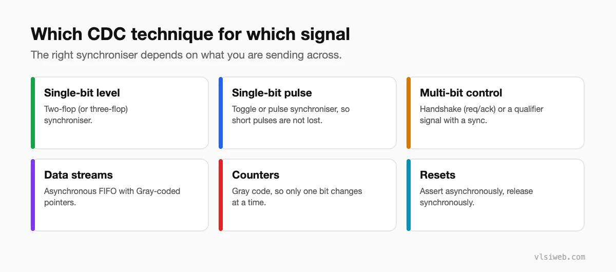
- Handshake: hold the data stable, send a synchronised request, wait for a synchronised acknowledge. See handshake synchronisers.
- Asynchronous FIFO: for continuous data streams. See asynchronous FIFO design.
- Gray code: for counters, so only one bit changes at a time.
- Qualifier (enable) synchronisation: keep a data bus stable and synchronise a single valid signal that tells the destination when to sample it.
Part 6: Rules I would always follow
- Know every clock in your design and which ones are asynchronous to each other.
- Register a signal in its source domain before it crosses.
- Use the right synchroniser for the kind of signal, and only one synchroniser per signal.
- Do not let the same signal cross through two different synchronisers and then recombine (reconvergence).
- Run structural CDC checks; simulation will not catch most of these bugs. See CDC verification.
Practise this on VLSI Forge
I built VLSI Forge so you can write RTL in your browser, run it on a real simulator and check every signal in the waveform. Free, nothing to install.
CDC and RDC problems · RTL Design problems
FAQ
Does a two-flop synchroniser remove metastability?
No. It makes the chance of a metastable value propagating so small that the MTBF becomes years or centuries. It does not make it zero.
Why must the input to a synchroniser come from a flop?
Combinational logic can glitch. A glitch can be captured by the synchroniser and look like a real transition.
Is CDC an issue between clocks of the same frequency?
Yes, if they come from different sources. Even a tiny frequency difference means the phase drifts and data will eventually change near the capturing edge.
What is reconvergence in CDC?
When signals synchronised separately are combined again in the destination domain. Because each may resolve on a different cycle, the combination can be wrong for a cycle.
