

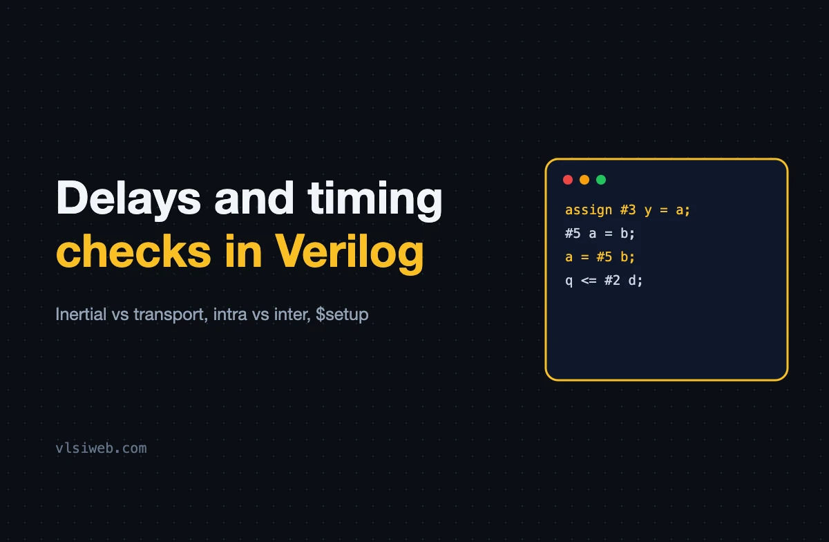
The short answer: Delays in Verilog (#n) only affect simulation; synthesis ignores them. A delay before a statement (#5 a = b;) waits and then evaluates, while a delay inside it (a = #5 b;) evaluates now and assigns later. Continuous assignment delays are inertial, so they filter pulses shorter than the delay; non-blocking intra-assignment delays (q <= #2 d;) behave like transport delays. Timing checks such as $setup, $hold and $width live in specify blocks and are used in gate-level and cell models.
You’ll rarely write delays in RTL, but you’ll read them in testbenches, behavioural models and gate-level netlists, and they are a favourite interview topic. This post combines my older posts on delay modelling, inter vs intra-assignment delays and timing checks.
- Time units: `timescale
- Inter vs intra-assignment delays
- Inertial vs transport delay
- Rise, fall and min:typ:max delays
- Specify blocks and timing checks
- Rules for RTL
Table of Contents
Part 1: Time units: `timescale
`timescale 1ns / 1ps    // unit / precision

#10      // 10 ns
#2.5     // 2.5 ns, rounded to the 1 ps precision
Every file that uses delays should have a timescale, or inherit one consistently. Mismatched timescales between files are a classic source of testbench confusion.
Part 2: Inter vs intra-assignment delays
| Code | What happens |
|---|---|
| #5 a = b; | Wait 5 units, then read b and assign it to a |
| a = #5 b; | Read b now, wait 5 units, then assign the old value to a (the block waits too) |
| a <= #5 b; | Read b now, schedule the update 5 units later, and continue immediately |
initial begin
  b = 1;
  #5  a = b;      // a = 1 at time 5
  b = 0;
  a = #5 b;       // reads b = 0 at time 5, a = 0 at time 10
end
The non-blocking form (q <= #1 d;) is sometimes used in RTL to make waveforms easier to read, by showing outputs changing just after the clock edge. It’s harmless for synthesis but I don’t recommend it in new code; it can hide real race problems.
Part 3: Inertial vs transport delay
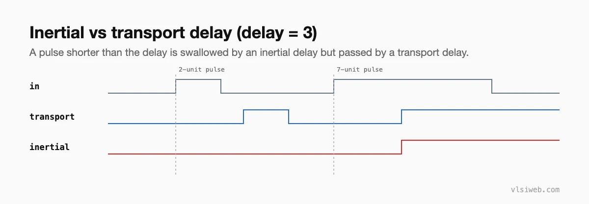
assign #3 y_inertial = in;            // inertial: like a real gate

always @(in) y_transport <= #3 in;    // transport: like an ideal wire
Real gates can’t respond to pulses shorter than their delay, which is what inertial delay models. A transport delay passes every pulse, which suits wire delays and some behavioural models.
Part 4: Rise, fall and min:typ:max delays
and #(2, 3) g1 (y, a, b);          // rise 2, fall 3
buf #(1:2:3) g2 (z, y);            // min:typ:max, chosen at compile time
You’ll see these in gate-level models. In real flows, accurate delays come from SDF files produced by STA tools and back-annotated into gate-level simulation.
Part 5: Specify blocks and timing checks
module dff_model (input d, clk, output reg q);
  specify
    (clk => q) = (0.12, 0.10);           // clock-to-q path delay
    $setup(d, posedge clk, 0.05);
    $hold (posedge clk, d, 0.03);
    $width(posedge clk, 0.20);
  endspecify
  always @(posedge clk) q <= d;
endmodule
Timing checks report violations during simulation, which matters in gate-level simulation with real delays. Cell libraries are full of them. In RTL simulation there are no real delays, so timing correctness is checked by static timing analysis instead.
Part 6: Rules for RTL
- No delays in synthesisable RTL; synthesis ignores them, so they only create simulation-synthesis mismatches.
- Use delays freely in testbenches for stimulus and clock generation.
- Never rely on #0 to fix a race; fix the race with non-blocking assignments.
- Keep one `timescale for the whole testbench environment.
Practise this on VLSI Forge
I built VLSI Forge so you can write RTL in your browser, run it on a real simulator and check every signal in the waveform. Free, nothing to install.
Previous in my Verilog series: FSMs in Verilog. Next: Tasks and functions.
FAQ
Are delays synthesisable in Verilog?
No. Synthesis tools ignore # delays. Real delays come from the gates and wires after synthesis and are checked by STA.
What is the difference between inter- and intra-assignment delay?
An inter-assignment delay (#5 a = b;) waits before evaluating; an intra-assignment delay (a = #5 b;) evaluates now and assigns after the delay.
What is an inertial delay?
A delay that ignores input pulses shorter than itself, like a real gate. Continuous assignment delays in Verilog are inertial.
What are $setup and $hold?
System timing checks used in specify blocks to flag setup and hold violations during gate-level simulation.
