

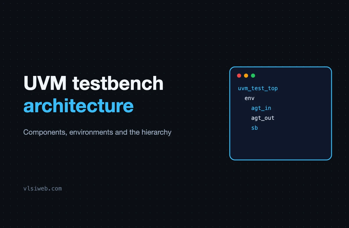
The short answer: A UVM testbench is a tree of components. The test (uvm_test) sits at the top and builds an environment (uvm_env), which contains one agent per DUT interface plus scoreboards, coverage collectors and often a register model. Each agent holds a sequencer, a driver and a monitor (or only a monitor if it’s passive). Components are created in build_phase, connected in connect_phase and do their work in run_phase; the hierarchy gives every component a unique path name.
Once you can picture the component tree, any UVM testbench becomes readable. This post covers the tree itself, the uvm_component base class, and how environments are put together. It combines my older posts on UVM testbenches, components and environments.
- The hierarchy
- uvm_component vs uvm_object
- Building an environment
- The top module
- Designing for reuse
Table of Contents
Part 1: The hierarchy
Part 2: uvm_component vs uvm_object
| uvm_component | uvm_object | |
|---|---|---|
| Lifetime | Whole simulation | Created and discarded freely |
| Has a parent and path | Yes | No |
| Takes part in phases | Yes | No |
| Examples | test, env, agent, driver, monitor, scoreboard | sequence item, sequence, config object |
| Constructor | new(string name, uvm_component parent) | new(string name = “”) |
Part 3: Building an environment
class my_env extends uvm_env;
  `uvm_component_utils(my_env)
  in_agent      agt_in;
  out_agent     agt_out;
  my_scoreboard sb;
  my_coverage   cov;

  function new(string name, uvm_component parent);
    super.new(name, parent);
  endfunction

  function void build_phase(uvm_phase phase);
    agt_in  = in_agent::type_id::create("agt_in", this);
    agt_out = out_agent::type_id::create("agt_out", this);
    sb      = my_scoreboard::type_id::create("sb", this);
    cov     = my_coverage::type_id::create("cov", this);
  endfunction

  function void connect_phase(uvm_phase phase);
    agt_in.mon.ap.connect(sb.exp_imp);     // inputs: predict
    agt_out.mon.ap.connect(sb.act_imp);    // outputs: compare
    agt_in.mon.ap.connect(cov.analysis_export);
  endfunction
endclass- Always create components with
type_id::create(name, this)so the factory can override them. - Pass
thisas the parent; that’s what builds the tree. - Connect TLM ports in connect_phase, after everything exists.
Part 4: The top module
module tb_top;
  logic clk = 0;
  always #5 clk = ~clk;
  stream_if vif_in(clk), vif_out(clk);
  dut u_dut (.clk, .in(vif_in), .out(vif_out));

  initial begin
    uvm_config_db#(virtual stream_if)::set(null, "uvm_test_top.env.agt_in*",  "vif", vif_in);
    uvm_config_db#(virtual stream_if)::set(null, "uvm_test_top.env.agt_out*", "vif", vif_out);
    run_test();
  end
endmodule
The static world (DUT, interfaces, clocks) lives in the top module; the dynamic world (classes) starts at run_test(). The configuration database is the bridge. See configuration and uvm_config_db.
Part 5: Designing for reuse
- One agent per interface protocol, packaged with its sequence items and sequences as a reusable VIP.
- Make agents active or passive by configuration, so a block-level env can be reused at chip level with the same monitors.
- Keep DUT-specific checking in the env (scoreboard, model), not in the agents.
- Use configuration objects for every knob, so tests never reach inside components.
Practise this on VLSI Forge
I built VLSI Forge so you can write RTL in your browser, run it on a real simulator and check every signal in the waveform. Free, nothing to install.
Previous in my UVM series: What is UVM?. Next: Sequence items.
FAQ
What are the main components of a UVM testbench?
Test, environment, agents (sequencer, driver, monitor), scoreboard, coverage collector and often a register model.
What is the difference between uvm_component and uvm_object?
Components form the static testbench hierarchy and take part in phases; objects are data like transactions, sequences and configuration.
What is uvm_test_top?
The instance name UVM gives the test created by run_test(); it’s the root of the component hierarchy.
Why create components with type_id::create?
So the factory can substitute a derived class from a test without changing the environment code.
