

The short answer: Boolean algebra is the maths of true and false (1 and 0) that every digital circuit is built on. With a handful of laws, especially distributive, absorption and De Morgan’s theorems, you can simplify logic expressions, which means fewer gates, less area and less delay.
You will not write Boolean proofs at work, but you will use these ideas constantly: reading synthesis results, simplifying conditions in RTL, and answering interview questions. Here are the laws that matter and how to use them.
- The basic operations
- The laws you will use most
- A worked simplification
- De Morgan’s theorems in practice
- SOP and POS forms
Table of Contents
Part 1: The basic operations
| Operation | Symbol | Result is 1 when |
|---|---|---|
| AND | A · B | both inputs are 1 |
| OR | A + B | at least one input is 1 |
| NOT | A’ | the input is 0 |
Everything else, including XOR, NAND and full adders, is built from these three.
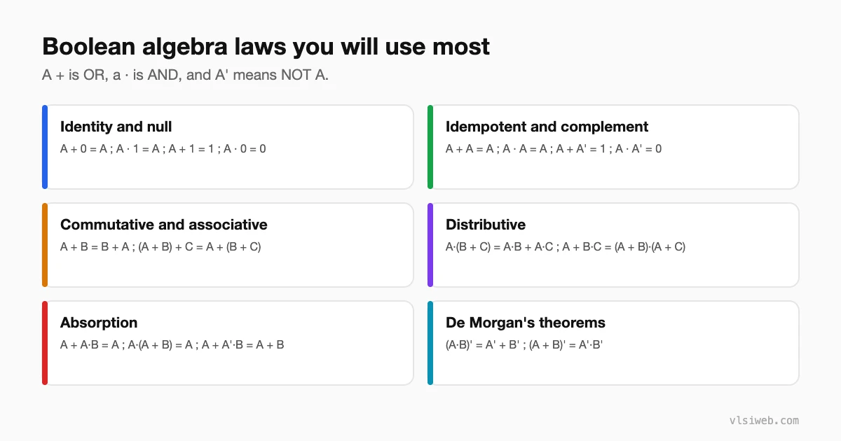
Part 2: The laws you will use most
Part 3: A worked simplification
Simplify F = A·B + A·B’ + A’·B:
F = A·B + A·B' + A'·B
  = A·(B + B') + A'·B      distributive
  = A·1 + A'·B             complement
  = A + A'·B               identity
  = A + B                  absorption (A + A'B = A + B)
Three gates and two inverters became a single OR gate.
Part 4: De Morgan’s theorems in practice
De Morgan’s theorems let you swap AND for OR by inverting inputs and output: (A·B)’ = A’ + B’ and (A + B)’ = A’·B’. This is why NAND and NOR gates can implement any function, and why synthesis tools freely move inversions around. In RTL, it also helps when you need to flip an ‘if all ready’ condition into an ‘if any not ready’ one.
Part 5: SOP and POS forms
- Sum of products (SOP): OR of AND terms, for example A·B + C·D. Maps naturally to AND-OR or NAND-NAND logic.
- Product of sums (POS): AND of OR terms, for example (A + B)·(C + D). Maps to OR-AND or NOR-NOR logic.
- Minterms and maxterms: SOP and POS written with every variable in every term. They are the starting point for Karnaugh maps.
Practise this on VLSI Forge
I built VLSI Forge so you can write RTL in your browser, run it on a real simulator and check every signal in the waveform. Free, nothing to install.
FAQ
What is the difference between Boolean algebra and normal algebra?
Variables only take 0 or 1, and some rules differ: for example A + A = A and A + 1 = 1.
Why simplify Boolean expressions?
Simpler expressions need fewer gates, which means less area, less power and usually less delay.
Do synthesis tools simplify logic for me?
Yes, very well. You still need Boolean algebra to understand what the tool did and to write clear RTL.
What is the duality principle?
Swapping AND with OR and 0 with 1 in a valid identity gives another valid identity.
