

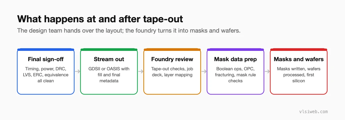
The short answer: Tape-out is the point where the final, fully signed-off layout is streamed out as GDSII or OASIS and sent to the foundry. The foundry then runs its own checks and mask data preparation: Boolean layer operations to derive mask layers, optical proximity correction (OPC) so shapes print correctly, fracturing into shapes the mask writer can draw, and mask rule checks. Masks are written and inspected, and wafers are processed, giving first silicon weeks or months later.
Tape-out is the milestone every chip team works towards. After it, changes become very expensive: a bug found later may need new masks, which at advanced nodes costs a great deal. This post covers what has to be ready at tape-out and what happens to the data afterwards. It replaces my older post on mask data preparation.
- The flow
- The tape-out checklist
- Mask data preparation
- Full masks, MPW and metal ECOs
- After first silicon
Table of Contents
Part 1: The flow
Part 2: The tape-out checklist
- Sign-off STA clean in every scenario, with waivers reviewed.
- IR drop, EM and power analysis within budget.
- DRC, LVS, ERC, antenna and density clean with the foundry’s latest decks.
- Equivalence checks between RTL, synthesis netlist and final netlist.
- DFT: test patterns generated and coverage targets met.
- Seal ring, logos, alignment marks and test structures in place.
- The final GDSII/OASIS re-verified as streamed out, not just the P&R database.
Part 3: Mask data preparation
| Step | What it does |
|---|---|
| Boolean operations | Derive the actual mask layers from drawn layers |
| Optical proximity correction | Distort shapes so they print as intended after lithography |
| Resolution enhancement | Assist features, phase shifting, and multiple-patterning decomposition |
| Fracturing | Convert polygons into the simple shapes mask writers can draw |
| Mask rule check | Make sure the mask shapes can be manufactured and inspected |
Most of this is done by the foundry or a mask shop. Design teams mainly need to deliver clean data with the right layer map and metadata.
Part 4: Full masks, MPW and metal ECOs
- A full mask set is used for production chips.
- Multi-project wafers (MPW) share one mask set between many small designs, which makes test chips and university projects affordable.
- If a bug is found late, a metal-only ECO using spare cells needs only the upper (metal) masks to be remade, which is much cheaper than a full respin.
Part 5: After first silicon
Bring-up and post-silicon validation start as soon as packaged parts arrive: power-on, clocks, scan tests, then functional tests at speed and across temperature. My post on verification vs pre- and post-silicon validation covers that stage.
Practise this on VLSI Forge
I built VLSI Forge so you can write RTL in your browser, run it on a real simulator and check every signal in the waveform. Free, nothing to install.
Physical Design problems · Static Timing Analysis problems
Previous in my physical design series: PPA and low-power PD. Next: Advanced nodes and 3D ICs.
FAQ
What is tape-out?
The release of the final, signed-off layout data (GDSII or OASIS) to the foundry for mask making.
What is mask data preparation?
The process of turning layout data into mask-ready data: layer operations, OPC, fracturing and mask rule checks.
What is OPC?
Optical proximity correction: modifying layout shapes so that, after lithography, they print on the wafer as the designer intended.
What is an MPW?
A multi-project wafer, where several designs share one mask set to reduce cost, typically for prototypes and test chips.
