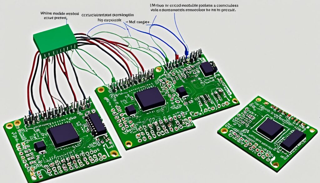
In the world of Verilog design, module instantiation plays a crucial role in creating efficient and scalable designs. We, as designers, understand the significance of utilizing this powerful feature to create hierarchical structures in our designs. In this article, we will explore the concept of module instantiation in Verilog and discuss its importance in the design process.
Table of Contents
What is module instantiation?
In Verilog, module instantiation is the process of creating instances of reusable modules within a larger design. It allows for hierarchical design, where complex systems can be built by combining simpler modules. This modular approach enhances the readability, scalability, and maintainability of the Verilog design.
When a module is instantiated, a new instance (or copy) of that module is created. Each instance is independent and can have its own set of inputs, outputs, and internal logic. These instances interact with each other through module connections, forming the overall design.
Module instantiation is an essential concept in Verilog as it promotes code reuse and modularity. By creating reusable modules, designers can efficiently build complex systems by instantiating these modules multiple times, each with its unique set of inputs and outputs.
Let’s take a closer look at how module instantiation works and its significance in Verilog design.
Advantages of module instantiation in Verilog
- Modularity: By breaking down a complex design into smaller, reusable modules, it becomes easier to understand, modify, and debug the code. Modules can be independently developed, tested, and verified.
- Code Reusability: Instantiating modules allows designers to reuse the same module in multiple instances within a design. This reduces the effort required to write and maintain code, leading to faster development cycles.
- Scalability: Modular designs can be scaled easily by instantiating additional copies of a module. The connections between modules can be modified as required to adapt to different system requirements.
- Design Abstraction: Modules provide a higher level of abstraction, allowing designers to focus on specific functionalities without worrying about the internal implementation. This promotes better organization and separation of concerns.
Module instantiation in Verilog provides the foundation for hierarchical design and promotes efficient and reusable code. In the next section, we will explore the syntax used for module instantiation in Verilog.
Syntax of module instantiation
In Verilog, module instantiation is a fundamental concept that allows us to create instances of reusable modules within a larger design. To understand module instantiation fully, it is essential to be familiar with the syntax used to instantiate modules in Verilog. In this section, we will explore the syntax in detail, including the module name, instance name, input/output ports, and any optional parameters.
The syntax for module instantiation in Verilog follows a specific pattern. Let’s break it down:
Module name:
The module name indicates the specific module being instantiated. It serves as a reference to the module’s definition and functionality. When instantiating a module, we need to specify the module name to ensure proper linkage with the module’s implementation.
Instance name:
The instance name represents a unique identifier for each instance of a module. It distinguishes one instance from another, allowing us to refer to specific instances and establish communication between modules. The instance name is used to connect input and output ports of the instantiated module with other modules in the design.
Input/Output ports:
The input and output ports of a module define the signals that can be sent to or received from the module. When instantiating a module, we need to connect the input and output ports with appropriate signals or wires for proper communication. This step enables the exchange of data and control signals between different modules in the design.
Optional parameters:
In some cases, modules may have optional parameters that can be specified during instantiation. These parameters can modify the behavior or configuration of the module. When instantiating such modules, we can provide values for these optional parameters to tailor the module’s functionality according to our requirements.
Here’s an example of the Verilog module instantiation syntax:
| Module Instantiation Syntax |
|---|
| module_name instance_name (input_port_1, input_port_2, …, output_port_1, output_port_2, …); |
The table above demonstrates the general structure of a module instantiation statement in Verilog. The module name is followed by the instance name, and then the input and output ports are listed within parentheses. The example illustrates a basic instantiation with input and output ports connected.
Understanding the syntax of module instantiation is crucial for designing complex systems in Verilog. By properly instantiating modules and connecting their input and output ports, we can create hierarchical designs that facilitate modularity, reusability, and scalability.
Connecting modules through instantiation
In module-based design, connecting modules through instantiation is a vital aspect of building complex and scalable systems. This process allows for the interconnection of different modules, enabling seamless data flow and communication between them.
Using Wire or Reg Data Types
One method of connecting modules in Verilog is by utilizing wire or reg data types. These data types serve as conduits for exchanging signals between modules and facilitate the intermodule communication.
Wire data type: The wire data type is primarily used for connecting output ports of one module to the input ports of another. It acts as a pathway for transferring data between modules.
Reg data type: On the other hand, the reg data type is typically employed for connecting input ports of one module to the output ports of another. It functions as a storage element, maintaining the state of the connected signal.
Different Ways to Connect Inputs and Outputs
When connecting modules through instantiation, there are various methods to establish the connections between the input and output ports:
- Direct connections: In this approach, the input and output ports of the modules are directly connected using the wire or reg data types. This method simplifies the interconnection process by directly mapping signals between modules.
- Buffered connections: Buffering is employed when the input and output ports have different drive strengths. It ensures proper signal propagation by adding an intermediate buffering module between the interconnected modules.
- Bidirectional connections: Bidirectional connections are used when a module has both input and output ports that need to transmit and receive signals. Special care must be taken to enable proper bidirectional communication by using tri-state buffers.
- Encoded connections: Encoded connections involve transforming the signals from one module to a different encoding scheme before connecting them to the input ports of another module. This technique is used for efficient data transmission and compatibility between modules using different encoding formats.
The table below provides a summary of these different connection methods:
| Connection Method | Description |
|---|---|
| Direct connections | Input and output ports connected directly using wire or reg data types |
| Buffered connections | Intermediate buffering module added to ensure proper signal propagation |
| Bidirectional connections | Tri-state buffers used for enabling bidirectional signal transmission and reception |
| Encoded connections | Signals transformed to a different encoding scheme for compatibility and efficient data transmission |

By understanding and implementing these different connection methods, designers can establish robust and efficient intermodule communication, facilitating the creation of complex and highly functional systems in Verilog.
Instantiating modules in real-world examples
Now that we have covered the fundamentals of module instantiation in Verilog, let’s dive into some practical examples to illustrate how it is used in real-world design scenarios. By showcasing these examples, we can gain a better understanding of how to effectively instantiate modules and connect them to achieve the desired design flow.

Example 1: Arithmetic Logic Unit (ALU)
One common application of module instantiation in Verilog is the design of an Arithmetic Logic Unit (ALU). An ALU performs arithmetic and logical operations, such as addition, subtraction, multiplication, and bitwise operations, on binary data.
| Module | Description |
|---|---|
| ALU | The top-level module that instantiates various sub-modules to perform specific operations |
| Adder | A sub-module responsible for performing binary addition |
| Multiplier | A sub-module responsible for performing binary multiplication |
| LogicUnit | A sub-module responsible for performing bitwise logic operations |
In this example, the ALU module instantiates the Adder, Multiplier, and LogicUnit modules, each responsible for a specific operation. By modularizing the design, we can easily reuse and connect these modules to create a versatile ALU capable of performing multiple operations.
Example 2: Memory Controller
Another practical example of module instantiation can be seen in the design of a Memory Controller. A Memory Controller manages the operations and data transfers between a CPU and memory devices.
| Module | Description |
|---|---|
| MemoryController | The top-level module that instantiates various sub-modules to control and manage memory operations |
| AddressDecoder | A sub-module responsible for decoding memory addresses |
| DataBuffer | A sub-module responsible for buffering and managing data transfers |
| ControlLogic | A sub-module responsible for controlling memory operations based on signals from the CPU |
In this example, the MemoryController module instantiates the AddressDecoder, DataBuffer, and ControlLogic modules to perform specific functions within the memory control system. By breaking down the design into modular components, we can easily manage and connect these modules to ensure efficient memory operations.
These practical examples of module instantiation in Verilog demonstrate the power and flexibility it offers in designing and organizing complex digital systems. By creating reusable modules and connecting them appropriately, we can achieve a scalable and efficient design flow for various applications.
Conclusion
Throughout this article, we have explored the concept of module instantiation in Verilog and its significance in the design process. Module instantiation allows for hierarchical design by creating instances of reusable modules within a larger design, promoting modular and scalable designs.
We discussed the syntax used to instantiate modules in Verilog, including the module name, instance name, input/output ports, and optional parameters. By understanding the syntax, designers can effectively connect modules and ensure proper data flow between them.
Real-world examples showcased the practical applications of module instantiation in Verilog. From complex system designs to smaller subsystems, the ability to instantiate modules and connect them allows for efficient design reuse and simplifies the overall design flow.
In conclusion, mastering module instantiation in Verilog is crucial for designing efficient and scalable systems. By harnessing the power of module instantiation, designers can create modular designs, enhance reusability, and streamline the design process. Whether working on small projects or large-scale designs, a deep understanding of module instantiation in Verilog enables designers to create robust and flexible designs.

